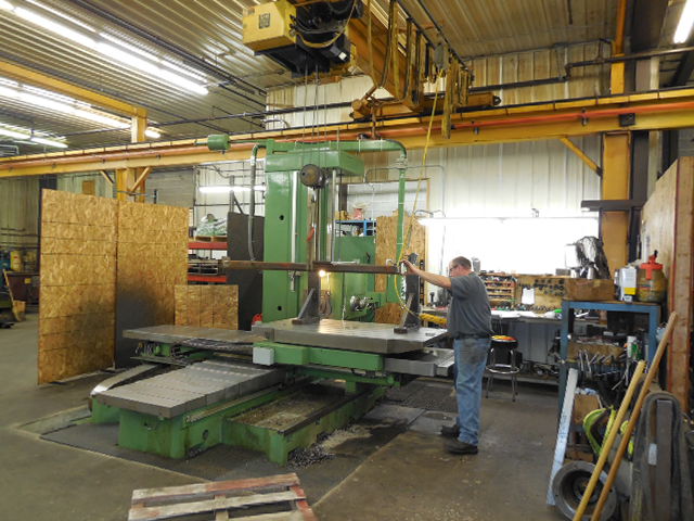
While our CNC boring bars are ideal for heavy duty, close tolerance operations; our manual bars are just as accurate and better suited for lower-volume projects.
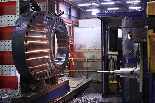
We accurately mill surfaces, bore holes, drill and tap, or cut large cavities in work pieces weighing up to 20 tons on our CNC boring bars.
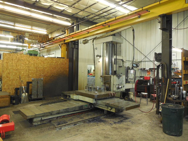
TOS WHQ 13 is our largest table type boring mill.
Our Toshiba BTD-200QH boring bars, equipped with probes and a full “B” pallet system, enable us to cost-effectively run production parts with a positioning accuracy of +1/-.0003 mm.
For continuous 4-axis machining operations, we make use of our BP-130R and BTD-110.R16 CNC boring bars with probes and full rotary tables.
Equipment Specifications
CNC Boring Bars
CNC Max: 196.85″
Manual Boring Bars
Manual Max: X: 160″ Y: 66″
Our Machines
TOS WHQ 13
Heid TS Inferred Probe
Maximum Workpiece Weight: 20 T
Table Size: 70.86″ x 98.42″
X-travel: 196.85″, Y-travel: 118.11″, Z-travel: 78.75
Toshiba BP-130R.22
Full “B” With Probe
Table Size: 70.8″ X 86.6″
X-travel: 160″, Y-travel: 100″, Z-travel: 60″
Toshiba BTD-200QH (2)
Full “B” Pallet System with Probe
Two 40″ x 48″ Tables
X-travel: 59.1″, Y-travel: 47.2″, Z-travel: 27.6″
Toshiba BTD-110.R16
Full “B” Probe
Table Size: 55.1″ x 63″
X-travel: 78.7″, Y-travel: 59.1″, Z-travel: 57.1″
TOS WHQ 13
Table Size: 70.8 x 86.6″
X-travel: 137.8″, Y-travel: 98.4″, Z-travel: 49.21″
SCHARMANN Dekamat WF 100
Fixed Table: 50″ x 144″
Two 60″ x 80″ Rotary Tables
X-travel: 160″, Y-travel: 60″, Z-travel: 80″
Summit BH110
Table Size: 55″ x 60″
X-travel: 75″, Y-travel: 66″, Z-travel: 52″
Wotan B130S
Rotary Table: 59.75″ x 66.75″
X-travel: 76″, Y-travel: 65″, Z-travel: 60″
Wotan B105M
Table Size: 55″ x 72″
X-travel: 78″, Y-travel: 65″, Z-travel: 50″
Capabilities
Drilling
Tapping
Milling
Sawing
Machining
Coating
Grinding
Honing
Painting
Sandblasting
Heat Treating
Welding
Internal Keyways
Surface Grinding
Manual Turning
Plasma Cutting
Painting
Aluminum
Brass
Bronze
Cast Iron
Copper
Stainless Steel
Steel
Break Discs
Castings
Energy Field Parts
Forgings
Heavy-Equipment Parts
Construction Equipment
Heavy Lifting
Marine
Mining
Packaging & Printing
Paper
Pipeline & Pipeline Repair
We can produce prototype and one-off runs to high volume production numbers; however, our niche remains in low-volume, large-part machining.
Lead time: 4 weeks, typically
We currently use Solidworks, AutoCad and Mastercam programming with direct control link. Our computer system is networked to all manufacturing phases.
Documents and file transfers via e-mail include: quotes, drawings, photos, spread sheets, 3D models/assemblies and CAD files.
Accepted drawing formats include:
.igs/.iges
Inventor
Solid Edge
AutoCAD (DWG)
DXF – Drawing Interchange Format or Drawing Exchange Format
PDF
SolidWorks (SLDPRT, SLDDRW, SLDDRT)
STEP – Standard for the Exchange of Product Model Data